What Is UART on a Router? How to Identify and Use It

I. A brief introduction to UART
Most routers today include a UART interface connected to the system processor. Its pins are routed to the printed circuit board (PCB) to support debugging, firmware replacement, or connection to serial devices such as modems.
A router normally starts with its built-in bootloader. The bootloader handles the first steps of locating firmware, checking hardware, and launching the system. During these early stages, it often outputs information through a serial port and may respond to its own command set. These are not commands from a normal operating system; they are predefined commands built into the bootloader. Different bootloaders from different vendors have different command sets.
Serial (UART) can be very useful. It may help recover a bricked router, but incorrect handling can also brick the device.
A router’s UART header commonly has five or four pins, depending on the manufacturer. In most cases, a UART interface has at least four pins: VCC, GND, RX, and TX.
Each board may use a different layout and location. The interface may be exposed as drilled holes, pin headers, or solder pads covered with a thin layer of solder.
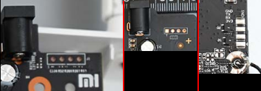
To use the UART port, you need a USB-to-UART adapter. Many adapters are available on the market, using different ICs such as PL2303, CH341A, CH340, CP2102, and FT232.
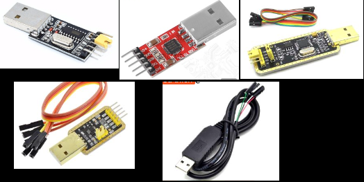
I use this FT232 adapter. It has RX and TX indicator LEDs, its driver is easy to install, and it uses an IC from a well-known manufacturer.
II. How to identify UART pins
Pay particular attention to the VCC pin. On many boards, VCC is pin 1, or it may be marked with a square or triangle. It will usually look different from the other three pins. Some manufacturers also print the pin order on the board.
In most cases, the VCC pin is not needed and can be left disconnected. Most routers I have worked with only require GND, RX, and TX. Use VCC only when you fully understand what you are doing. Using the VCC pin incorrectly can damage the USB adapter, kill the CPU, or cause a short circuit and fire on the router’s mainboard.
- There are generally two ways to identify UART pins with a multimeter.
- Method 1: Use the DC voltage range.
- Measure as follows: The GND pin is connected to board ground and will have continuity with the adapter GND pin and the negative terminal of a capacitor. |Measure between|GND|and|VCC|-> 3.3V| |—|—|—|—|—| ||VCC|and|RX|-> 0V| ||VCC|and|TX|-> 0V| ||GND|and|RX|-> 3.3V| ||GND|and|TX|-> 0V| ||RX|and|TX|-> 0V|
- Method 2: Use the resistance range.
- Measure as follows: |Measure between|Approximate range| |—|—| |GND and GND|0 Ohm| |GND and VCC|5k - 200k Ohm| |GND and TX|8k - 2M Ohm| |GND and RX|10k - 8M Ohm|
- Method 1: Use the DC voltage range.
After identifying GND, RX, and TX, connect the adapter to the PC.
III. Connecting the UART pins to the USB adapter
Mark the three identified pins on the mainboard. If the UART header consists of drilled holes, you can use three 1 mm copper wires, sharpened at one end, and hold them firmly in the GND, RX, and TX holes.
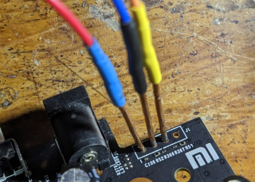
- Connect the router GND pin to the USB GND pin.
- Connect the router RX pin to the USB TX pin.
- Connect the router TX pin to the USB RX pin.
Example:
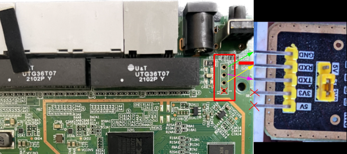
After completing the connections, connect the USB adapter to the PC.
IV. PC software for controlling the serial port
- Plug the adapter into the PC. The required driver depends on the IC used by the adapter.
- Identify the IC in your adapter so that you can download the correct driver.
- For example, if you use this FT232 adapter, download its driver from the manufacturer’s website (FT232 driver).
- Several applications can control a COM port on a PC, including PuTTY, MobaXterm, and TeraTerm.
For example, using MobaXterm:
- After installing the USB adapter driver, open Device Manager > Ports (COM & LPT). Look for a device named USB Serial Port (COMx), where COMx is the assigned port number, such as COM3, COM4, or COM7.
- Open MobaXterm, choose Session > Serial, select the COM port identified above, and set Speed (bps) to
115200. Each bootloader may use a different bitrate; output appears only when the correct rate is selected. Click OK. - Power on the router. If the UART connection is correct, many lines of output will appear.
That is the basic process. If anything is unclear, leave a comment and I will try to help. Good luck!
Comments & Discussion
Share your thoughts, ask questions and feedback